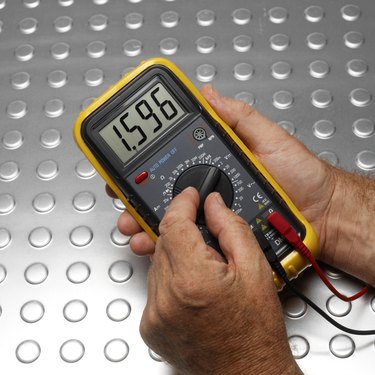
The motherboard of a computer provides the platform for the majority of the machine's components, allowing the use of complex circuitry without needing confusing wiring schematics. Testing or troubleshooting a PC motherboard can be done at home, as a simple multimeter can be used to test various circuits and determine general electronic problems.
Testing the DC Voltages
Video of the Day
Step 1
Make sure the 20-pin ATX connector is in and the computer is hooked up to AC power. Set the multimeter to 20V DC. Using the black multimeter probe, probe the backside of the connector and set the black probe in contact with pin 15, 16, or 17 (GND pins).
Video of the Day
Step 2
Use the red probe to probe the following pins (looking for the readings indicated in the parentheses): Pin 9 (Purple, VSB) should be at 5 V (any other reading indicates a problem with the PSU); and Pin 14 (Green, PS On) should be between 3 and 5 volts. Press the PC power switch, and the PS_On value should drop to 0. Other readings indicate a faulty switch.
Step 3
Use the red probe to check Pin 8 (gray, Power_OK), which should be above 2.5 V; this signals that it is okay for the computer to start. Pressing reset should make the Power_OK reading drop to 0 and then climb back up.
Testing the PSU and Motherboard for Short/Open Circuits
Step 1
Unplug the computer from AC power and allow several minutes for any excess charge to drain. Set the multimeter to the lowest Ohm setting (around 200) and touch the leads of the probes together to zero the meter. Touch the two leads to the bare metal of the computer's chassis; the zero reading should be the same.
Step 2
Carefully remove the ATX connector from the motherboard. Keep the black probe on the metal of the chassis and use the red lead to check the PSU's A/C ground pin and the black wire pins on the D/C connector; these should all read zero.
Step 3
Keep the black lead on the chassis and use the red probe to check the values of the colored wire pins on the D/C connector. All colored wires should give a reading of 50 or greater.
Step 4
Remove the CPU from the motherboard socket. Use the ATX 20-pin chart to refer to pin numbers on the board's connector. Keep the black lead on the chassis and use the red lead to test the GND pins on the motherboard connector: Pins 3, 5, 7, 13, 15, 16, and 17 should return a reading of zero. Any other reading indicates a possible faulty connector.