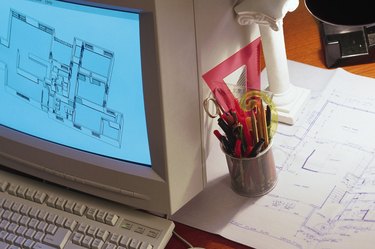
Constraints are imposed conditions, rules or limiting factors. Geometric and numeric constraints occur in engineering and computer-aided design, with applications in a number of mechanical design areas, including architectural drafting and robotics. There is a clear difference between a geometric constraint and a numeric constraint. Simply put, a geometric constraint relates to other parts of a geometric figure, whereas a numeric constraint is a set number not relative to other parts of a design. Both geometric and numeric constraints define the dimensions of objects in computer-aided design, or CAD, modeling systems.
Types of Geometric Constraints
Video of the Day
Geometric constraints define specific points on geometric objects and determine their orientations to other objects. Some examples of geometric constraints include parallelism, perpendicularity, concentricity and symmetry. Parallelism occurs when two or more lines or axes of curves are equidistant from each other. Perpendicularity is a constraint in which lines or axes of curves intersect at right angles. Concentricity arises when two or more arcs, circles or ellipses share the same center point. Symmetry occurs when selected lines or curves become symmetrically constrained around a selected line. A CAD-based method called "geometric constraint solving" involves finding the configurations of lines, points, circles, and other geometric figures that are constrained to have established relationships to each other.
Video of the Day
Types of Numeric Constraints
Numeric constraints are simply number values. They can be integers or algebraic equations used to control the dimensions or location of a geometric figure. A numeric constraint can refer to measurements such as distance and size, while limiting the range of those possibilities. The length, width and depth of a geometric figure are examples of numeric constraints. Numeric constraints impose restrictions on designs because they do not change in relation to other geometric objects.
Geometric Constraints in AutoCAD
Using the AutoCAD software application, you can constrain two geometric objects by performing certain commands. For example, you can select a location on a figure and then select a location on another figure that will move toward the first until those selected points coincide. Until you remove the constraint, these objects will continue to have this relationship. If you use a command on a constrained object, it affects the other objects that depend on the constraint. For example, when you constrain two objects to be symmetrical, rotating the line of symmetry will rotate the constrained objects as well. The "Auto Constrain" feature in AutoCAD applies a set of constraints automatically, depending on your choice of objects.
Geometric Constraints in TurboCAD
TurboCAD is another computer-aided design program that uses constraints. TurboCAD's specific constraints feature is called the "Constraint Manager," which automates the process of working with different types of constraints. It allows you to manipulate the spatial relationship between objects and develop predictive outcomes during the design modification process. Using constraints properly is an effective, time-saving technique as you execute your design. There are comprehensive tutorials available, both online and offline, providing step-by-step instructions on how to use TurboCAD's "Constraint Manager."